
Complete product specifications
Support customization
PRODUCTS
MESSAGE
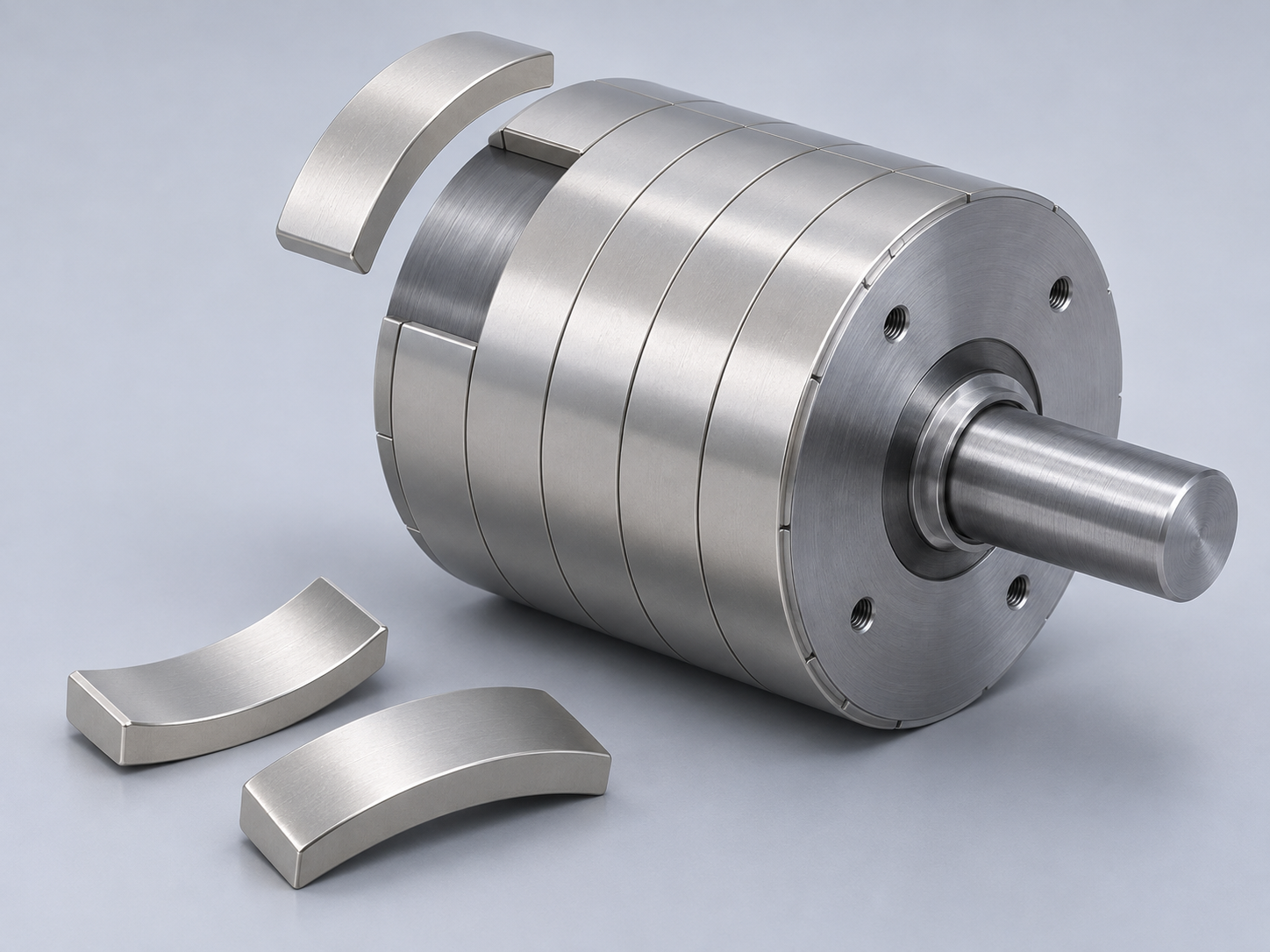
Why do some motors have 12 slots, while others use 24 or 36? Do more slots mean smoother operation? If the goal is to reduce noise and torque ripple, will switching to a stronger magnet help?
In permanent magnet motors, performance depends on the interaction between the stator, windings, and rotor magnets. Understanding the role of motor slots also helps engineers and buyers specify motor magnets more accurately.
What Are Motor Slots, and How Do They Differ from Magnets?
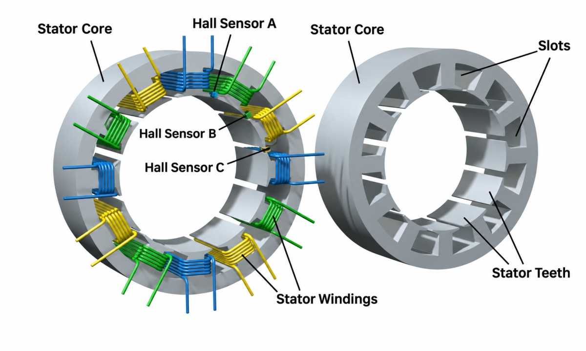
In a typical slotted, inner-rotor permanent magnet motor, slots are distributed around the inner circumference of the stator core. They accommodate winding conductors and insulation. The core sections between adjacent slots are called teeth, which form part of the magnetic circuit and guide magnetic flux.
The permanent magnets on the rotor provide the excitation field. When the stator windings are energized in the required sequence, their magnetic field interacts with the rotor field to produce torque.
Stator slots accommodate the windings, while rotor magnets establish the permanent magnetic field. The two interact through the magnetic field in the air gap.
It is also useful to distinguish between two types of slots: stator winding slots generally contain conductors, while magnet slots in an interior permanent magnet rotor hold the magnets.
Why Do Motors Use Different Slot Counts?
Windings must be arranged around the circumference in a defined pattern. Slots provide specific positions for the conductors. Changing the slot count changes the available winding layouts and the spatial distribution of the winding magnetic field.
With a suitable design, additional slots can offer more options for optimizing winding distribution. However, more slots do not necessarily mean lower torque ripple or noise. Performance also depends on the pole count, winding configuration, slot openings, magnet dimensions, and other structural parameters.
For a motor of the same size, increasing the slot count also requires redistributing slot width, tooth width, and insulation space. It may make lamination manufacturing and winding insertion more difficult. Slot count must therefore be selected according to performance targets and manufacturing requirements.
Why Must Slot Count Be Considered Together with Pole Count?
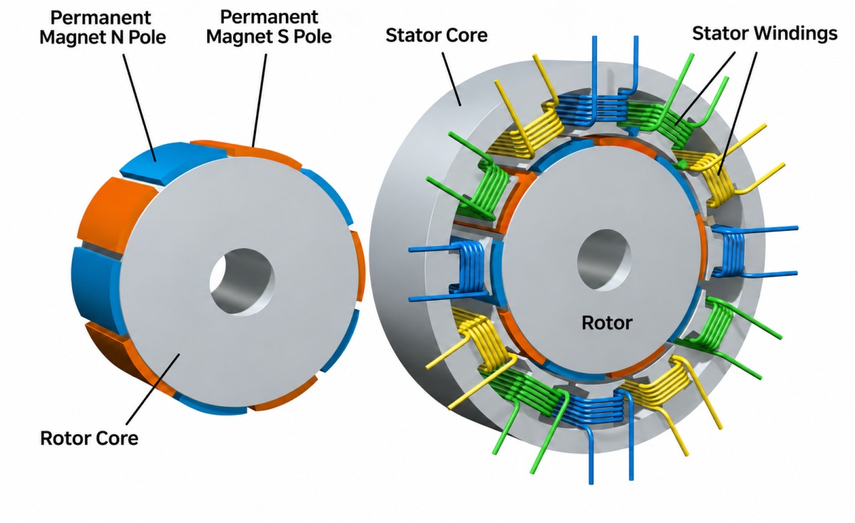
The term “12-slot, 10-pole” describes two separate parameters:
The slot–pole combination affects winding arrangements and the periodic variation of the magnetic field. It is an important part of permanent magnet motor design.
Cogging torque results from the interaction between the permanent magnet field and the stator’s toothed structure. It can occur even when the windings are not energized. Besides the slot–pole combination, magnet width, slot openings, and magnet skew also affect cogging torque. Increasing the slot count or selecting a higher magnet grade alone does not guarantee lower cogging torque.
Also, the number of magnetic poles does not necessarily equal the number of individual magnets. One pole may consist of several magnet segments, while a single ring magnet can be magnetized to create multiple poles. A 10-pole rotor does not automatically require 10 individual magnets.
How Do You Select Rotor Magnets After Defining the Slot–Pole Configuration?
For magnet procurement, slot and pole counts provide application context. To establish magnet specifications that can be manufactured and inspected, the following requirements must also be defined.
1. Select the Magnet Shape Based on the Rotor Structure
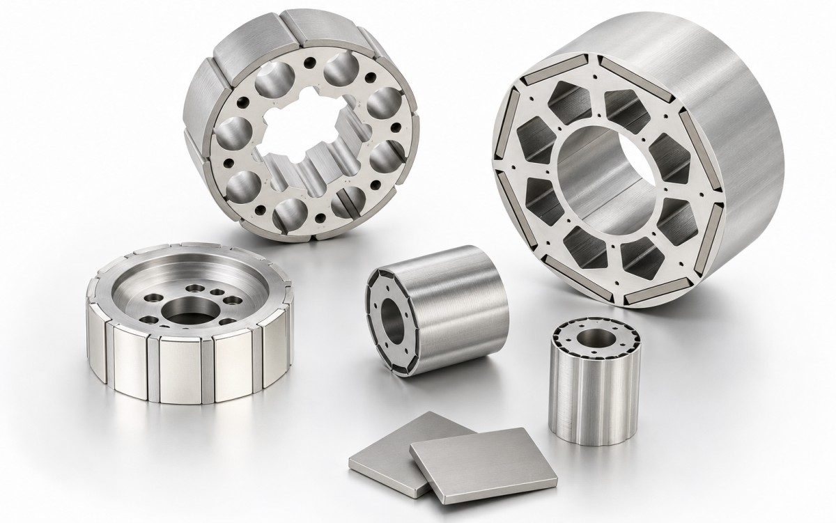
Different rotor structures require different magnet geometries and mounting arrangements.
The shape must be determined together with the magnetic circuit and assembly method. For example, the arc angle of an arc magnet affects pole coverage, making it more than just a mechanical fitting dimension.
For magnet selection, click: Arc Magnets or Neodymium Magnets.
2. Select the Material and Grade Based on Temperature and Demagnetization Risk
Motor magnet selection should go beyond comparing magnetic strength at room temperature.
Neodymium magnets can be considered for compact designs requiring high magnetic performance. Samarium cobalt magnets can be evaluated for applications requiring greater magnetic stability at elevated temperatures.
The specific selection must account for the magnet’s actual operating temperature, opposing magnetic fields, and operating point in the magnetic circuit. A higher maximum energy product does not automatically mean greater resistance to demagnetization.
For example, a robot joint motor and an electric vehicle traction motor may both use neodymium magnets but require different grades because of differences in temperature rise, load, and rotor structure.
3. Specify the Magnetization Direction and Pole Arrangement
Two magnets with identical shapes can produce different magnetic fields in the rotor if their magnetization directions differ.
RFQ drawings should specify the magnetization direction, north pole location, and required arrangement of magnets in the rotor. For arc magnets, radial magnetization must be distinguished from parallel magnetization along a fixed direction. For multipole ring magnets, the pole count, pole positions, and magnetized regions must be defined.
These requirements must be evaluated against the material, geometry, and magnetizing fixture capabilities. They should not be assumed from the magnet’s shape alone.
4. Specify Dimensional Tolerances and Magnetic Requirements Separately
Meeting dimensional specifications does not guarantee that a magnet will meet the magnetic requirements of the design. Similarly, comparable surface gauss readings at a single point are insufficient to establish that two magnet batches will perform identically.
Procurement specifications can define the following separately:
- Dimensions: Finished dimensions after coating, tolerances, chamfers, and critical mating surfaces.
- Magnetic properties: Material grade, magnetization direction, and magnetic characteristics to be verified.
- Measurement conditions: For magnetic flux or surface field measurements, specify the fixture, probe position, measurement distance, and temperature.
- Batch requirements: Agree on sampling methods and batch records according to the project’s needs.
Clear specifications help suppliers understand the requirements and support consistent acceptance of both samples and production batches.
What Information Should You Provide When Requesting a Magnet Quotation?
Saying that a magnet is “for a 12-slot, 10-pole motor” helps the supplier understand the application, but it is not enough to define the magnet specifications.
To reduce back-and-forth communication, provide the following information:
If the material or grade has not yet been selected, you can start by sending the available drawings, operating temperature, and application requirements, then provide additional design information as it becomes available.
Please give us a message
Beijing Saint Langma Magnetic Industry Technology Co., Ltd.